
Patch cords are usually bought as a commodity, and that is precisely why they cause quiet problems. A cord is not a part number: it is the physical result of a series of systems decisions — how far the link runs, how dense the rack is, which transceiver sits at each end, who has to find that cable at two in the morning, and what happens the first time somebody plugs it into the wrong port. Make those decisions deliberately and the cord disappears into the network. Leave them to a default and you find out at commissioning, when the cabinet is already full.
A recent enquiry makes the point. A customer who provides field operations and remote support for data halls sent us a single trial order: twelve different specifications, ten cords each, all OS2 single-mode duplex round cords with LSZH 2.0 mm jackets — 120 cords in total. Beyond the specification itself there was one hard requirement: a length tolerance of ±2 cm. That is tighter than the ±5 cm or ±10 cm that patch cords are normally quoted to, and it only makes sense if somebody had already measured the cabinet runs and worked out how much slack the routing would really tolerate.
Nothing in that order was exotic. What made it work was that each of the twelve specifications was a decision rather than a guess. This article is the order in which we recommend making those decisions, and the criteria that separate one reasonable answer from another.
1. Start with the fiber, not the connector
Fiber choice is driven by distance and by the optics you plan to plug into each end — in that order. Everything else, including jacket colour and price, follows from it.
Single-mode OS2
OS2 single-mode fiber is the default for structured backbones and for anything beyond a short in-hall reach. Most OS2 sold today is bend-insensitive: G.657.A1 and G.657.A2 are the two families you will see quoted, and both remain compatible with the older G.652.D. The difference is how tightly they can be bent before macro-bending loss appears; A2 tolerates a tighter radius than A1. In a data hall that matters for a very practical reason: cords are dressed around panel edges, bundled behind trays and routed through spaces nobody designed for a fiber. Bend-insensitive fiber buys margin exactly where the installer is working one-handed in a dark cabinet.
Multimode OM4 and OM5
Multimode is cheaper to light. Short-reach optics for multimode cost less than the equivalent single-mode transceivers, and that saving usually dwarfs the difference in cord price. OM4 has been the workhorse inside the hall for years; OM5 adds a wider usable window, which matters if you plan to run several wavelengths over the same fiber. The deciding factor is not the cable but the transceiver plan and how long you expect it to stay in service. If you cannot yet say which optics will sit at each end, choose the fiber that keeps the most options open rather than the cheapest cord on the quotation.
Jacket colour follows the fiber according to the customary convention — yellow for OS2, aqua for OM3/OM4, lime green for OM5. Treat colour as a convenience, never as a specification: the label and the test report identify a cord, not its jacket.
2. Then the cable construction
Construction is where a quote can look identical and the delivered goods be wrong for the job. Four choices decide it.
Simplex or duplex
Duplex means two fibers in one cord — one transmit, one receive — and is the normal choice for a switch-to-panel link. Simplex carries a single fiber and belongs on access-side work and test leads. If a port needs both directions on separate fibers, it needs duplex; ordering simplex to save space is a common and expensive mistake.
900 µm, 2.0 mm or 3.0 mm
- 900 µm tight-buffered — the smallest option, and the one that packs the most fibers behind a panel. It also offers the least protection: the buffer is the only thing between the fiber and the world, so it needs proper strain relief and careful handling.
- 2.0 mm round — the current default for data-centre patching. Small enough for high-density routing, robust enough for daily re-patching. When someone asks for a cord that is both dense and durable, this is usually the answer.
- 3.0 mm round — the traditional telecom diameter. More crush resistance and more protection, at the cost of roughly half the routing density and a stiffer cord that is harder to dress in a tight cabinet.
Zip (flat) duplex or round duplex
A zip duplex cord is two round legs joined by a thin web: convenient when the two ends land on different panels, because the legs can be separated. A round duplex cord puts both fibers inside a single round jacket; it resists crushing better, sits tidier in a bundle, and does not split when it is dragged past a cable tie. In dense cabinets the round construction wins. Where the two halves of a link genuinely go to different places, zip is easier to work with. Decide which of those two problems you actually have.
Jacket material and flame rating
LSZH (low smoke, zero halogen) compounds are the usual choice where people, equipment and cable share a room, and where local codes restrict halogenated jackets. PVC remains common where the specification is older and the budget tighter. Flame ratings matter just as much and are a separate question: cable routed through an air-handling space is normally required to carry a plenum rating, while a riser rating suits vertical runs in a shaft. Halogen content and flame rating both belong on the purchase order, written as two separate requirements. The materials we supply for these constructions are RoHS- and REACH-compliant, and declarations are available on request.
Polarity
A duplex link has a direction: position A transmits into position B. In structured cabling the polarity method has to match the way the patch panels were wired, which is why the TIA-568 polarity methods exist as a family — a straight A-to-B arrangement plus the crossed variants — rather than as one universal rule. A duplex cord with the wrong polarity produces a link that only works when you move both ends, a fault that looks like an optics problem and is not. If your field teams re-patch often, buy cords whose polarity can be changed in the field instead of cords that have to be replaced.
3. Connector choice: LC, SC and the details that matter more
LC dominates the data centre for one reason: density. Its 1.25 mm ferrule is roughly half the size of the 2.5 mm ferrule used by SC, so an LC panel holds about twice as many ports in the same footprint — and high-density switches and pluggable optics are built around that size. SC is larger, but it is far from finished: it is everywhere in existing installations and in equipment designed around it, and it is easier to handle with gloves on.
Two details matter more than the connector family:
- The latch. An LC connector latches with a small clip that becomes hard to reach in a fully populated panel. A push-pull boot lets a technician release the connector by pulling the boot instead of fishing for the latch — the difference between a two-second re-patch and a twenty-minute one.
- The duplex clip. A clip holds two LC connectors in the correct orientation and at the correct spacing. Field-swappable clips let the polarity of a cord be changed without buying a new cord.
If a cord is going to be re-patched regularly — and in a data hall it will be — those two features are worth more than a fraction of a decibel.
4. Ferrule material: the component that decides stability
The ferrule is the precision part: a cylinder with a bore down the middle that holds the fiber so its core sits at the exact centre of the mating surface. It is also the component buyers ask about least, which is unfortunate, because it decides how stable the loss stays over temperature and over thousands of re-mates.
Zirconia ceramic — the mainstream
Ceramic ferrules are made from zirconia and are the default for data-centre patching. The reason is dimensional: the material has a low coefficient of thermal expansion, high hardness and excellent stability, so the bore stays concentric and the carefully ground end-face geometry stays put through temperature cycles and repeated mating. A ceramic ferrule does not deform under the spring load that presses the two end-faces together, which is what keeps insertion loss and return loss repeatable. Within the word ceramic there are grades: bore diameter tolerance and concentricity are where the extra cost sits, and ferrule tolerance is the single most useful question to ask a supplier.
Stainless steel
Metal ferrules survive abuse. They resist impact and edge damage better than ceramic, which makes them relevant in industrial and field environments where connectors are handled roughly and cleaned in a hurry. The trade-off is precision: holding a stable ground end-face geometry and a tight bore tolerance is harder in steel, and the material behaves differently under temperature. Metal is a sensible answer where mechanical survival outweighs the last fraction of a decibel, and rarely the right answer for a data hall.
Composite and engineering plastic
Moulded ferrules keep unit cost down for short-life, low-mating-count applications. Their limits are exactly where data centres live: frequent re-mating, tight loss budgets and long service life. They are not the material for a cord that will be moved every quarter for ten years.
Whichever material you choose, the specification that matters is concentricity — the offset between the bore and the ferrule axis. Every micron of eccentricity becomes lateral misalignment between two fiber cores, and misalignment is insertion loss. A supplier who quotes ceramic ferrule without a tolerance has told you very little. Two parts act with the ferrule and deserve the same attention: the spring that loads it, and the alignment sleeve in the adapter, normally a ceramic split sleeve whose job is to hold two ferrules on one axis.
5. End-face polish: PC, UPC and APC
All three polishes answer one question: how the two end-faces meet. PC (physical contact) domes the end-face slightly so the fibers touch instead of leaving an air gap. UPC (ultra physical contact) does the same with a tighter domed radius and a finer surface, which lowers return loss. APC (angled physical contact) grinds the end-face at an 8° angle so that light reflected at the interface is bent out of the fiber instead of travelling back towards the transmitter.
- UPC is the data-centre norm. Switch ports, transceivers and panels are almost always UPC, normally colour-coded blue, and typical return loss is on the order of ≥ 50 dB.
- APC is normally green and reaches around ≥ 60 dB, which is why it belongs wherever back-reflection hurts: analog and RF-over-fiber links, CATV, and PON access networks.
- PC still exists in older installations and some legacy equipment.
One rule is not negotiable: UPC and APC must never be mated. An angled face against a flat face contacts only along one edge, leaving an air gap over the core and concentrating pressure on a small area — high loss, unstable reflection and a real risk of damaging both end-faces. Because colour is only a convention, the reliable check is the end-face itself, or the label, or the test report.
6. Setting the performance grade — and testing for it
Two standards do most of the work when a cord specification is written.
IEC 61753-1 groups connector performance into grades, quoted most often as Grades B, C and D, with progressively tighter insertion loss and return loss limits as the grade rises. The grade you buy should follow from the link budget: on a long, loss-limited span, or in a patching field where many connectors add up, the tighter grade pays for itself; on a short intra-rack link it does not. Write the grade and the limits you will accept onto the purchase order instead of assuming a default.
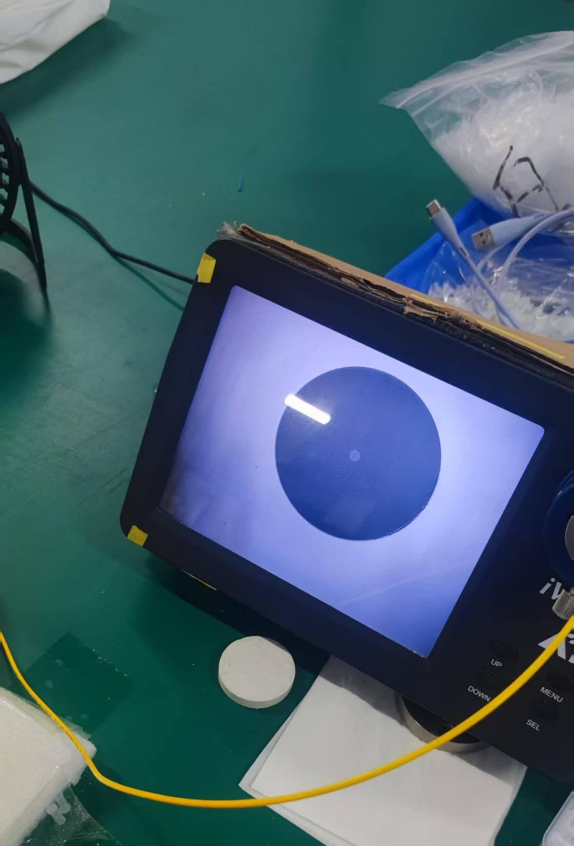
IEC 61300-3-35 is the standard for end-face inspection and acceptance criteria. It defines how an end-face is judged — scratches and defects assessed by zone, from the core outward through the cladding, adhesive and contact zones — and those limits depend on the fiber size and connector type. This is why “the end-face looks clean” is not an inspection: the criterion is zone-by-zone, and a cord can pass insertion loss testing while failing visual inspection, or fail a return loss limit while looking perfect to the eye.
End-face geometry is the third measurement and the one most often skipped. Three values describe the polished dome, and they are measured with an interferometer:
- Radius of curvature — how domed the end-face is. Too large and the two faces may not make full contact; too small and the contact area collapses towards a point, concentrating stress.
- Apex offset — how far the top of the dome sits from the fiber axis. An off-centre apex tilts the contact geometry, which shows up as loss and poor repeatability.
- Fiber height — how far the fiber sits above or below the surrounding ferrule. It must stay inside a narrow window: too high and the fiber can be damaged at the contact point, too low and there is a gap.
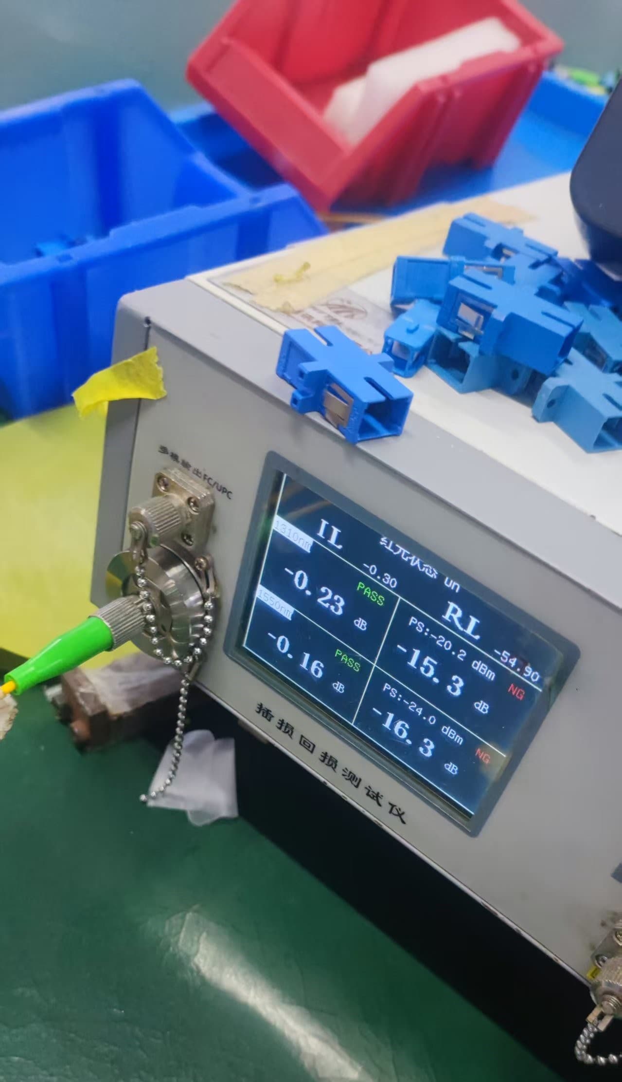
A test report that deserves the name should contain, per cord or per batch as agreed: an identifier linking the cord or batch to the report; the connector type and polish; the wavelengths tested, normally 1310 nm and 1550 nm for single mode; insertion loss and return loss for each fiber and each direction as specified; the limits that were applied; the end-face inspection result with the criteria used; end-face geometry results on sampled or specified parts; and the date and lot identification. If a supplier cannot say which limits were used, the numbers are decoration. Such a report is available on request.
7. Mechanical and environmental limits
Four figures decide whether a cord survives its first year in service.
- Minimum bend radius, quoted twice — once for the cord installed and static, and once for the tighter radius allowed while it is being pulled into place. Bend-insensitive fiber raises the fiber's own tolerance, but the jacket and strength members still set the cable's limit. Being explicit about which figure applies to which stage prevents most bend damage.
- Tensile strength, also in two forms: the load the connector can take without the fiber moving inside the ferrule, and the load the cable itself can carry. The classic failure is a cord pulled by its jacket while the connector is jammed in a panel.
- Operating temperature — indoor patch cords are built for indoor conditions. Outdoor, aerial and industrial runs need a wider range and a different jacket compound, and the epoxy holding the fiber in the ferrule has its own working window.
- Mating durability — the number of re-mates a connector is expected to survive while staying inside its loss limits. Ceramic ferrules in a ceramic sleeve are stable well beyond the cycle counts ordinary patching produces, but every cycle drags the two end-faces across each other: a dirty connector damages both sides, and repeated damage is indistinguishable from a bad cord.
8. Labels, packaging and traceability
For a team that has to find cords inside a rack, the label is a functional part of the product, not an accessory. It has to reproduce the specification — mode, connector, polish, length — and carry a batch or serial identifier that ties the cord to its test record. It has to stay legible and stay attached through handling, and it has to agree with what was ordered.
Beyond the label: a dust cap on every connector; the packing you specified, from individual bags to bulk cartons to your own artwork and part numbers; the batch test report inside the shipment; and a packing list keyed to the batch identifiers, so a missing or wrong cord can be traced instead of argued about.
This is what makes a multi-specification trial order work. When twelve specifications arrive in one shipment, labelling is how the receiving team verifies that twelve distinct specifications were actually delivered, without counting and guessing. And a length tolerance of ±2 cm only means something if the length printed on the label is the length that was measured.
9. Before you ask for a quote: twelve questions
Answer these and a quotation stops being a range.
| # | Question | Why it changes the answer |
|---|---|---|
| 1 | Fiber type and grade (OS2 G.657.A1/A2, OM4, OM5) and the reach it must support | Sets the fiber and the colour, and rules out options that cannot hold the link budget |
| 2 | Connector per end (LC, SC, or hybrid) and whether the ends match | Decides ferrule size, panel density and which optics the cord can mate with |
| 3 | Simplex or duplex, and whether a duplex clip is required | One fiber or two, and how the pair is keyed and spaced |
| 4 | Polish per end (UPC, APC) confirmed to match at every mating point | Grinding step, achievable return loss, and the colour code |
| 5 | Performance grade and acceptance limits (Grade B, C or D; IL and RL targets) | Selects ferrule grade and decides how much testing the order carries |
| 6 | Ferrule material and bore / concentricity tolerance | Stability of loss over temperature and thousands of re-mates |
| 7 | Jacket material, diameter and flame rating (LSZH or PVC; riser or plenum) | Construction, cost, and whether the route is compliant |
| 8 | Length per specification and the tolerance you will accept | How cords are cut and verified; ± 2 cm and ± 10 cm are different production problems |
| 9 | Polarity method (straight, or a crossed method) and whether clips must be field-swappable | Whether the link still works after the first re-patch |
| 10 | Boot and strain relief (standard latch or push-pull) | How serviceable a fully populated panel really is |
| 11 | Label content, serialisation and packing format | How your receiving team verifies the delivery |
| 12 | Test report scope (per cord or per batch) and quantity per specification | Defines the test workload and the total order volume |
10. How we handle a multi-specification trial order
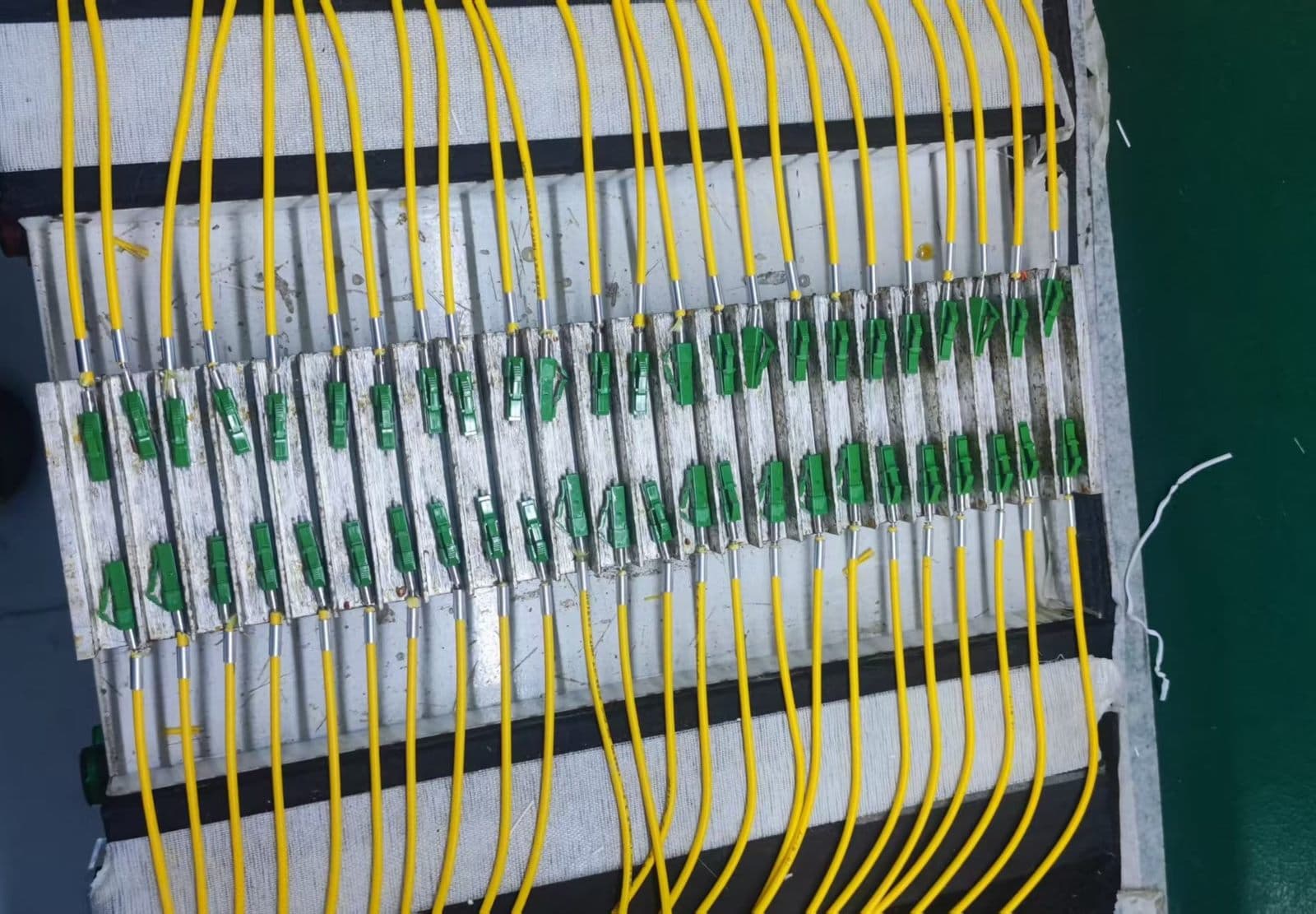
Twelve specifications of ten cords is not an awkward order for Hengchang Technology, because the specifications are scheduled together: the different types are produced in one production window so the order arrives as one shipment with one set of paperwork rather than as a trickle of partial deliveries. Every cord is measured for insertion loss and return loss before packing; end-face inspection and geometry measurements are performed on the parts the order specifies; and the batch report travels with the goods, so incoming inspection does not have to re-test a trial order end to end.
A tight length tolerance is the part of a trial order that has to be agreed before production rather than after. We cut and verify to the tolerance you set, and where a given construction or length makes that tolerance impractical, we say so before the order runs rather than shipping and hoping. If ±2 cm matters to your cabinets, it matters to us.
Send the specification — fiber, connector, polish, construction, length and tolerance, polarity, labelling and quantity — and we will come back with engineering questions if there are any, then a quotation. The full option list is on our fiber optic patch cord page, and constructions for harsher routes are on the armored patch cord page. When you are ready, send us the specification and our engineers will reply with the technical questions and the commercial answer in one pass.
Prefer email? Write to wangyazhong@hengchangtech.com, or reach us on WhatsApp +86 138 1667 2110.