
High-current connectors
XT30, XT60 and XT90 connectors — 20 A to 45 A, solder cups or PCB pins
XT30, XT60 and XT90 are paired high-current DC connectors used on lithium battery packs and power leads. Ours run 20 A to 45 A on 10–16 AWG, in solder-cup and PCB-mount versions, with an anti-spark option on XT90.
- 20 A to 45 A, 10–16 AWG, male and female as a pair
- Solder cup, PCB straight, right-angle and vertical
- XT90S anti-spark version for pack connection
- Custom tooling and seven-day prototypes
Range
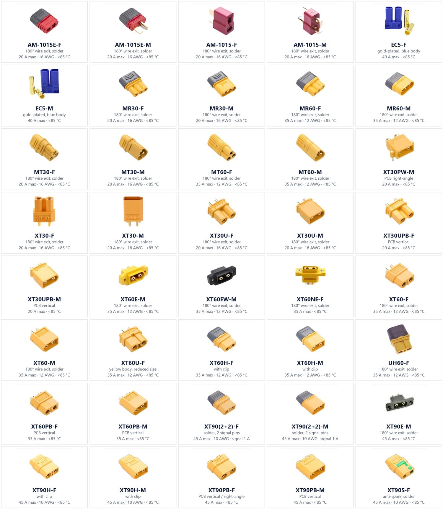
The whole high-current family, not only XT
XT is the most common series, but the same bullet-contact principle runs through the whole range below — which matters when one pack needs an XT90 for the main lead and an XT30 for the balance harness.
| Series | Max current | Wire size | Termination | Notes |
|---|---|---|---|---|
| XT30 | 20 A | 16 AWG | Solder cup / PCB pin | Straight, right-angle and vertical PCB variants |
| XT60 | 35 A | 12 AWG | Solder cup / PCB pin | Straight, vertical PCB and panel variants |
| XT90 | 45 A | 10 AWG | Solder cup / PCB pin | XT90 (2+2) adds two 1 A signal pins |
| XT90S | 45 A | 10 AWG | Solder cup | Anti-spark version for pack connection |
| EC5 | 40 A | 10 AWG | Solder cup | Gold-plated contacts, blue housing |
| MR30 / MT30 | 20 A | 16 AWG | Solder cup | Same bullet principle, smaller body |
| MR60 / MT60 | 35 A | 12 AWG | Solder cup | Larger body than MR30/MT30 |
| AM-1015 | 20 A | 14 AWG | Solder cup | Red housing |
| UH60 | 35 A | 12 AWG | Solder cup | — |
Every series is supplied as a male and female pair, with a 180° wire exit and a rating to 85 °C.
Model list
Part numbers in the current catalogue
The series table above is the family view; this is the part-number view. Use it to check whether the model you already have a drawing for is in production, or to find the PCB-mount equivalent of a wire-exit part.
| Series | Model | Rating / termination |
|---|---|---|
| XT30 | XT30-F / XT30-F.G.Y | 180° wire exit, 20 A max, 16 AWG, 85 °C |
| XT30 | XT30-M / XT30-M.G.Y | 180° wire exit, 20 A max, 16 AWG, 85 °C |
| XT30 | XT30U-F / XT30U-F.G.Y | 180° wire exit, 20 A max, 16 AWG, 85 °C |
| XT30 | XT30U-M / XT30U-M.G.Y | 180° wire exit, 20 A max, 16 AWG, 85 °C |
| XT30 | XT30UPB-F / XT30UPB-F30.G.Y | PCB vertical, 20 A max, 85 °C |
| XT30 | XT30UPB-M / XT30UPB-M30.G.Y | PCB vertical, 20 A max, 85 °C |
| XT30 | XT30PW-M / XT30PW-M30.G.Y | PCB right angle, 20 A max, 85 °C |
| XT60 | XT60-F / XT60-F.G.Y | 35 A max, 12 AWG, 85 °C |
| XT60 | XT60-M / XT60-M.G.Y | 35 A max, 12 AWG, 85 °C |
| XT60 | XT60U-F / XT60U-F.G.Y | 35 A max, 12 AWG, 85 °C |
| XT60 | XT60H-F / XT60H-F.G.Y | 35 A max, 12 AWG, 85 °C |
| XT60 | XT60H-M / XT60H-M.G.Y | 35 A max, 12 AWG, 85 °C |
| XT60 | XT60E-M / XT60E-M.G.Y | 180° wire exit, 35 A max, 12 AWG, 85 °C |
| XT60 | XT60EW-M / XT60EW-M.G.B | 35 A max, 12 AWG, 85 °C |
| XT60 | XT60NE-F / XT60NE-F.G.Y | 180° wire exit, 35 A max, 85 °C |
| XT60 | XT60PB-F / XT60PB-F30.G.Y | PCB vertical, 35 A max, 85 °C |
| XT60 | XT60PB-M / XT60PB-M30.G.Y | PCB vertical, 35 A max, 85 °C |
| XT90 | XT90E-M / XT90E-M.G.B | 180° wire exit, 45 A max, 85 °C |
| XT90 | XT90H-F / XT90H-F.G.Y | 45 A max, 10 AWG, 85 °C |
| XT90 | XT90H-M / XT90H-M.G.Y | 45 A max, 10 AWG, 85 °C |
| XT90 | XT90PB-F / XT90PB-F30.G.Y | PCB vertical, 45 A max, 85 °C |
| XT90 | XT90PB-M / XT90PB-M30.G.Y | PCB vertical, 45 A max, 85 °C |
| XT90 | XT90S-F / XT90S-F.G.Y | 45 A max, 10 AWG, 85 °C |
| XT90 | XT90(2+2)-F / XT90(2+2)-F.G.Y | 180° wire exit, 45 A max, 10 AWG, plus 1 A signal pins |
| XT90 | XT90(2+2)-M / XT90(2+2)-M.G.Y | 180° wire exit, 45 A max, 10 AWG, plus 1 A signal pins |
| AM | AM-1015E-F / AM-1015E-M | 20 A max, 16 AWG, 85 °C |
| AM | AM-1015-F / AM-1015-M | 20 A max, 16 AWG, 85 °C |
| ECS | ECS-F / ECS-M | 180° wire exit, 40 A max, gold-look blue housing |
| MR / MT | MR30-F / MR30-M, MT30-F / MT30-M | 180° wire exit, 20 A max, 16 AWG, 85 °C |
| MR / MT | MR60-F / MR60-M, MT60-F / MT60-M | 180° wire exit, 35 A max, 12 AWG, 85 °C |
| UH | UH60-F / UH60-F.G.Y | 35 A max, 12 AWG, 85 °C |
A model not on this list is not a refusal — it is a tooling question. Send the drawing and we will confirm whether it is a variant of an existing body or a new tool.
Variants
What actually differs between part numbers
Within one series the housing is the same; the differences are the termination and the retention. This is the list to check before you send a drawing.
XT30
- XT30-F / XT30-M — the standard pair, 20 A, 16 AWG, 180° solder cups
- XT30U-F / XT30U-M — reduced body for tight packs
- XT30UPB-F / XT30UPB-M — vertical PCB pins
- XT30PW-M — right-angle PCB pins
- XT30PWB-F / XT30PWB-M — vertical PCB pins, short tail
XT60
- XT60-F / XT60-M — the standard pair, 35 A, 12 AWG
- XT60U-F — reduced body
- XT60H-F / XT60H-M — with clip, higher retention
- XT60E-M / XT60EW-M — PCB mount, straight and right-angle
- XT60NE-F — PCB mount, no clip
- XT60PB-F / XT60PB-M — vertical PCB pins
XT90
- XT90-F / XT90-M — the standard pair, 45 A, 10 AWG
- XT90 (2+2)-F / -M — two 1 A signal pins alongside the power pair
- XT90H-F / XT90H-M — with clip
- XT90E-M — PCB mount
- XT90PB-F / XT90PB-M — vertical PCB pins
- XT90S-F / XT90S-M — anti-spark, green marking
Customisation
What we change, and what stays on existing tooling
Bodies come from tooling we already run, so a colour change or a lead assembly is a short job. Only a new housing or a new footprint needs a tool.
- Housing colour — black, yellow, red, blue, or your own colour
- PCB footprint — straight, right-angle or vertical pins, drawn to your board
- Lead assemblies — pre-soldered leads, cut to length, with or without sleeving
- Boots and caps — strain relief, panel-mount flange, protective cap
- Packing — bulk bag, mated pair per bag, or retail-ready pack
Process
Six steps, and a prototype in about seven days
MOQ and mass-production lead time are quoted per configuration rather than published as a single figure — a bare connector body and a terminated harness are different jobs, and publishing one number for both would mislead either way.
Step 1
Requirement — series, current, wire size and the environment it runs in
Step 2
DFM review — we check the footprint and lead geometry against your drawing
Step 3
Tooling — connector bodies come from existing tooling; leads and housings are drawn
Step 4
Prototyping in about 7 days
Step 5
Sample approval against the agreed drawing
Step 6
Mass production, with MOQ and lead time quoted per configuration
Quality
What you can write into the drawing
These are the checks a buyer can require on a connector order. Put the limits in the drawing and they go into our inspection plan for the run.
- Contact resistance limit for the mated pair
- Pull-force limit for the mated pair and for the lead joint
- Temperature-rise test at your rated current
- Plating thickness, where your market requires it
- AQL sampling level for incoming inspection
If your market requires a specific standard, name it and we will tell you whether the test can be run in-house or has to go to a third-party laboratory.
Related
Other assemblies from the same plants
Connectors, fibre and cable assemblies are produced in the same group, which is why a mixed order can leave on one container.
USB-C connectors and cable assemblies
C22 and C16A series receptacles, 240 W E-Marker assemblies and USB4 data cables.
EC5 jump starter cable
The 40 A EC5 body built into a complete jump-starter lead with reverse-polarity protection.
How OEM orders run
The six-step process from requirement to mass production, with the documents at each stage.
Buyer questions
Three things buyers ask first
What is the difference between XT60 and XT90?
Current rating and wire size. XT60 is rated 35 A on 12 AWG, XT90 is 45 A on 10 AWG and has a larger body. If the pack pulls more than about 35 A continuously, XT90 is the usual choice; below that XT60 keeps the assembly smaller and cheaper.
When should I use the XT90S anti-spark version?
When the connector is the first thing that closes the circuit on a high-current pack. The resistor in the S version limits the inrush, so the contacts do not arc when you plug in. On lower-current packs that XT60 covers, it is not needed.
Can you supply the connector already terminated with leads?
Yes. Send the wire gauge, length, stripping dimensions and whether you want sleeving or a boot, and we return a drawing for approval before anything is cut. Bare connectors ship from existing tooling; terminated assemblies are built to drawing.
Send the series, wire size and quantity
A drawing or a photo of the connector you are replacing is enough to start. We return a drawing and a quote matched to the configuration. wangyazhong@hengchangtech.com